Monday 11 November 2013

Back to the Boat - Cabin Fever

At last some free time to potter in the boatshed! Taking stock of where I last got to (it's been a while) I've been making some modification to Kees Prins "Far Fetch" plans.  The main mods done to date are lengthening the hull by 8 inches to 17 ft 5 inches, centering the outboard cut out and adding twin rudders. The remaining item I had not yet modeled was the cabin size and ergonomics. To do this I first built a "lining-off" jig out of quad aluminium tubing and plastic connectors. This sits on my workbench over the model and I can measure down from the centre bar into the hull to check all mods and also do final lining off of the whole model prior to modifying the original plans from Kees Prins and Iain Oughtred.  You will see a pic below showing me starting to use this with the work I am doing on cabin design.

First thing I did re cabin space was to add 2 inches to the sheer. You can see this in pic above - pretty rough planking with that gap there but I will fair it up later. This was a bit of a pain to do as I had already fitted an inwale on the previous sheer plank. Next I added deck beams at station 2, 3 and 6 (the main structural deck points where I would be playing with cabin shape) and then made a cardboard deck. I drew a preferred deck perimeter for the hull/deck joint and made (extended) focal point of these curves ending just in from the bow where the forestay is to be anchored (you will see this point used in later pic re cabin slope). I took lining off x,y,z's of these perimeters and played with them on Delft ship CAD to get fair lines then.  After many cups of tea and coffee sitting looking at various ideas I came up with the following cabin profile which gave me head space sitting up in the bunk and included an extended front cabin roof for a bit more airspace and dry storage (there will just be a deck beam there in the middle, not a bulkhead as in the mock up).

Now to make a more permanent cabin model which I have started in the next pic. I am making the whole cabin structure above deck as a separate item so I can lift it off and view internal space as more detailed internals are checked.

Here's an amended draft on Kees Prins plans to show the full extent of hull and sheer increase and the new cabin design (new profile lines in red). New cabin is (relative to waterline) 9 inches higher at rear, 3 inches higher at front (both include the extra 2 inches sheer) for main cabin section and the forward extension is 17 inches long.  Note that there will now be no anchor hatch - this will help maintain clear foredeck space given the extended cabin. I intend to keep the anchor and warp in a self contained box inside the hull.  I also have plans for a small dorade box in the front cabin section to improve hull airing in our hot humid climes here.
I suspect waterline will come up a bit with the added displacement from higher sheer and cabin profile and it is starting to look a bit more like a motor sailor but that's acceptable compromise for me.

Here's some more pics a few days later after adding some more realistic cabin facings. Umbrella pole is roughly where mast will be.


A view dead ahead from about waterline level....

...and side on at deck level with 15 degrees heel....on the wind.


Tuesday 22 October 2013

Sidetracks - New England in the Fall

We are not great world travelers but a long held ambition was to see New England in the fall. So we booked up this trip 12 months ago and so spent a glorious 8 days touring through Mass, Maine, New Hampshire and Vermont. I would like to have taken some sidetracks in Maine to Wooden Boat base and Eggomoggin Reach but our bus route wasn't close enough to do this. But we did spend two days on Mount Desert Island and I got my fill boating venues there.  With some guidance from Kees Prins (who had tracked around here shortly before our trip) we got to see some beautiful little harbours around the island.  We also used our free afternoon in Bar Harbour to do a scenic flight around the island and pass over 7 of the cute Maine coast light houses.  Here's an aerial shot of Somes Sound (John Brooks named his version of Herreshoff 12 1/2 after this).  It's the only fiord in the USA.

We happened to be there when the federal government shutdown was on so access to National Park was closed - see below at Arcadia National Park on Mount Desert Island this was a close as we could get to Cadilac Mountain.
Autumn leaves were near their peak throughout New England an here's a couple of glimpses.

Mt Washington

New Hampshire Lake at Rocky Gorge
Lexington Green near Boston

Saw the following model of Herreshoff J boat Reliance at MIT Marine engineering display in Boston


Sidetracks - Big Boat Cruising

Not much activity on the boat building front due to another semester of teaching underway and some family holidays. This first holiday was "Big Boat Cruising" to Vanuatu and New Caledonia. First time for my wife and I and reason was to accompany our live wire 93 year old Aunt on a food and lifestyle experience away from the boredom of retirement home. Here's a pic of our floating home in Vanuatu harbour - a very appealing harbour with sheltered coves (apart from cyclone season I guess!) and very pleasant locals.

 Under way, I found the balcony of our cabin the place to be - listening to the waves slip past the hull and the wind past the ears - mainly from the 15 knots of engine speed.  Too far from the water up on deck 11 for me - I'd much rather be on the deck of this ketch we saw slipping out of Noumea for an afternoon sail.  I'd saved up a book to read on the cruise which was equally nautical and absorbing - "The Great Race" by David Hill about the mapping of the coast of Australia by Mathew Flinders and simultaneous activities of French explorers to do likewise. 
 

Friday 26 July 2013

Model - Twin Rudders Version 2

Here's my second attempt at the twin rudder system. It's more compact and everything will fit within a decked narrow  intermediate section between the end of cockpit bulkhead and another bulkhead in front of the outboard well area.  Stern area is now very clean with just the push rods attached to the rudders and these have little lateral movement so will be scope for a couple of narrow hatches on the sides and plenty of buoyancy to be built in. I tried my hand at a video to demo the twin rudder system.


Thursday 11 July 2013

Model - Steering Systems and Twin Rudders

I'm now getting into uncharted waters - design variations not drawn by Iain Oughtred or Kees Prins - I will be getting back to them on this before the build. I wanted twin rudders so I can centrally locate the outboard and so steering on the wind and in rough water will give more efficient rudder control.  I also want to see if I can rig a removable stick rudder control in the cockpit as an option to a tiller (I will still have a tiller but linked to the same system controls).    Here's a few pics of a construction model I have set up specifically to test this out (and also test the cockpit people space).  Note my shop made mannequins of 1/5th size me and crew (note: crew has not committed to joining this ship yet).

Below is pic of transom with outboard cutout and sticks representing rudders (at 12 degree incline to vertical) and end of cockpit bulkhead. The rods at the top lead into the edge of the cockpit seat where the stick control attaches. The lever system here uses hobby shop ball joints - real boat would have stainless steel rodends and rod and system would be more compact than here. Rods will not project through the transom as shown here.


Here's the skipper and crew seated in the cockpit and the stick control in the skipper's left hand attached to the rod which feeds through the edge of the cockpit seat to behind the bulkhead. There's a fairly small arc of movement of the stick control (+/- 30 degrees) which transfers to +/- 45% at the stern where it meets the rudder cranks.  Leverage is provided by length of stick and rudder crank for about 4 to 1 ratio of effort. Above you will see a bar that ties the the two rudder controls together, low down just behind the bulkhead.

I'm not convinced this lever system is viable. Whilst it all works fine in model, the lever angles are not optimum and the system is cluttering up stern space for buoyancy and storage.  I am now starting work on a drum and rope system which will be more compact - but still including cockpit joystick and optional tiller (each removable). It will work off rudder cranks higher up on the transom and with less crank cutout in the transom. The outboard cutout will be reduced because I am now convinced I need long shaft rather than short shaft.  Current motor thinking is Tohatsu 4 stroke 6HP with external tank.

I'm happy with the cockpit space and the extra 5 inches I have added here by extending the stern.  The space between cockpit and transom will be taken up a short decked area with mainsheet traveler and removable gallows space and them followed by drainage well under the motor cutout and space for 12 litre fuel tank, fenders and wet weather gear storage - lots of buoyancy will be built it below this and along hull around this.


Thursday 20 June 2013

Model - Turnover celebrations

Well finally I got the planking finished and comes a time when we hold our breath and wonder if the hull will actually come off the jig. I had waxed the ribbands with parafin wax but still wasn't confident of an easy release because I wasn't able to get under the hull during planking to clean up epoxy (I will be able to do so on full scale build). Anyway a few squeezes and tap on planking and eventually she popped off with no damage. The building books say allow yourself a small celebration at turnover stage so I did just that (see below).

You will see in the top right I have managed to save the building jig without any damage so another model like this could be done by me or anyone else interested in the exercise.

Here's a closer view of the hull. There's a few rough spots and short cuts but I am pretty happy with the outcome given the purpose. I didn't cut conventional gains on planks at the bow (because the ply was too thin and brittle to cope with the chiseling) - instead I cut a full thickness rebate in the overlapped plank to give the same effect - I'll fill the air gap with some filleting.  I'm going to try for cutting gains at the stern on the full scale boat - it will be much prettier and avoid having to cut rebates in the transom.


Sunday 16 June 2013

Model - Planking Lessons

As mentioned earlier in this blog, one of my objectives in building a model of Skye Maid before the real boat is to put myself through a DIY boat building school (learn from mistakes cheaply) and get the logical order of doing things sorted in my mind. Despite reading lots of books, I forgot that I needed to allow for the thickness of overlapped plank edge when making patterns - that is until I got to the fifth plank as we round the bilge and plank shapes become their weirdest.  So from there on I moved straight to John How's method of making the plank patterns using two battens stuck together with criss cross sticks stuck with hot stick gun. Ian Oughtred also covers this approach on page 59 of his book but using screws instead of hotstick glue. Some pics and comments follow on my journey so far fitting planks to the model. You can easily ply apart these patterns after copying the plank shape and reuse the battens.

  
 In the above pic you can see the two battens, one clamped to the bottom edge of the last plank glued on, the other is clamped over the top of the next ribband below - this gives top and bottom edge of the next plank to be added. The cross sticks are then stuck on, to preserve the pattern allowing for the exact bent curvature of the plank.  Once unclamped, this pattern can be traced onto planking stock. Remember to mark key locating positions on the pattern (midship mould, bow, transom) before unclamping it and these marks need to be traced onto the planking stock as well as tracing plank edges.

The above pic shows the U shaped clamps I made to hold planks on (an Oughtred idea). The wedges I found at Bunnings for about $10 a box - in a range of different sizes - the wedge gap (plank to clamp) varies from top to bottom of plank because of extra thickness at the laps.


This pic is rather overexposed but it's starting to look like a hull with dry fit of the fifth plank added.

Sunday 28 April 2013

Boatshop Timber Rack

I had been awaiting a delivery of 10 sheets of 4mm genuine Bruynzeel Hectout Gaboon/Okume plywood. With the close down of Bruynzeel local distribution a couple of years ago, this has to be specially imported. After some research I found the only source for this was through Andrew Denman of Denman Marine in Tasmania. I had to wait about 3 months for Andrew to restock his supplies and my order arrived earlier than expected last week.  This made for a frantic construction of the A frame storage rack I had intended to build to fit this in my tiny boatshop (no space for the better horizontal stacking).  Anyway after a frantic day of construction and emptying out the boatshop I got it done and the ply unpacked and stacked - I'll finesse the clamping flat a bit further. Here's a pic 


The pic makes it look skew but believe me the rack is inline. I built in two shelves in the middle of the A frame which might be useful for stacking timber and various boat parts components. Also note 3 sets of wheels (two with brakes on)  to move it around the boat shop as necessary - gotta watch it doesn't get away from me with a slight gradient already in the boatshop and downhill driveway beyond. I'll be adding a mooring line to the back of the rack tethered to a cleat back there somewhere.  

Thursday 18 April 2013

Model - Plank Patterns & Stern Extension

Looking at a model from different directions gets you thinking whether your comfortable with the proportions of the boat. I already had a few thoughts yet to be settled re mast position and cabin size but the main thought on looking at the model is the stern looked chopped off too soon. Also the anticipated waterline being 3 inches higher gave part of the transom buried in the water. From my dinghy racing days I learned of the speed drop from dragging the back of the boat in the water. So I decided to extend the transom back 9 inches which should see its bottom just clear of the waterline and a bit of extra design length to fiddle with cabin shape and centreboard case positioning.  Here's the result of the change.


Now it's time to get the planking process underway.  The plan is to make cutting template patterns for the planks from thin light ply, then use these templates to cut one set of planking stock patterns (with generous trimming margin according to these templates), which will be then fitted and trimmed to perfect fit as the final version of patterns in stock thickness.  I am hoping these will be useful for the full size build (blown up 5 times) as templates for scarfing up stock for each plank pretty close to full size fit.

For the template patterns I am using 1mm Finish beech 'aircraft' plywood.  It's a bit expensive but I had some left over just enough to do do a full set of templates. It's light to handle and can be cut with a knife.

Here's some pics of the process of holding up the sheet to the model and progressively marking out and cutting the templates.  I hope to be able to remove most of the screws holding the ribands and glue these on and smooth the whole mould shape before I trim and dry fit final patterns from planking stock (this will be  2.7mm standard ply - 5 times this is a bit thicker than the 9mm ply I intend to use on the final boat but probably has more representative stiffness for the model than the thinner beech ply being used for templates).  Re the ribands I have been reminded  of the Tom Hill method which is to trim moulds by riband thickness and thus not have to rebate.  This gives more freedom to align them before fixing and no need to flatten moulds in between plank landings - I'll definitely be doing this on the final boat. 


Quite a stretch on available small clamps to be able to clamp the sheet and templates while they are fitted because of small gaps between ribands. Also had barely enough room to get my hand in under the jig to mark the sheet from underneath the ribands. By having most key points marked I was able to use a fairing batten to get the full template pretty close.

 It's good to mark each plank as you go for plank name, station positions and orientation.

 Leave trimming off both ends until the final planks are glued on the backbone - it's a bit of a disaster if you cut these off too short too early.  The forward overhang at the stem is referred to as "hoodends".  I got five plank templates out today - hopefully will finish the rest tomorrow.


Monday 15 April 2013

Model - Ribands On

I decided to rebate the moulds to fit ribands to the markings for plank edges. I figure working on my own this will make fitting the planking easier on the full size boat. Whilst Iain Oughtred's book does not encourage this he is Ok with it if you fair the ribands right up to the stem.  Here's the moulds below rebated to take the ribands.


I made another shop-made tool to help hacking out slots in the molds to get the ribands to sit in line with the mould edge as they twist along the hull.  It's manual jig saw - cut the shape of the top of the blade into a flat piece of brass, then added two other flat peices either side, plus mahogony handles and through bolts and voila - a hand made hand jig saw - a jigamething.

And after a lot of fiddling and a few broken ribands we have something starting to look like a boat.


Wednesday 10 April 2013

Model - Lining Off Lessons

The Mould coordinates came from my modelling process using DelftShip (CAD software covered in an earlier post). I started with Iain Oughtred's standard full scale mould plan drawings to get 3D coordinates for the Sheer line and outer edge of plank marks. These were then adjusted allowing for the "wedge insert" to expand the hull width and the raising of sheer line. Using Delfship I then faired lines and adjusted the initial station points to get something looking good for body and plan view lines. One further change I made was to pull out the tumblehome in the sheer at the transom. This was partly to provide a bit more width to play with the framing to support twin rudders and centered outboard.

So it was going to be interesting to see how all this translated to a real 3D view of the boat in the form of the moulds. Well it soon became pretty clear to me that the plank lands emerging from this modelling work were not going to give an even and pleasing view of planking. I think the mould shapes are pretty much OK but the positioning of the plank lands needs to be done from scratch. Of course in a full size build we would be sorting out the plank land markings on the moulds before we assemble them on the building jig. But I am not too worried about this, it's all part of lessons along the way. So I rig up a small ribbon tape measure to remark all the plank lands using Iain Oughtred's well thought out method in his Book Chapter 3 - Lining Off. He even has his percentages there for Fulmar which also helps. One good tip - for good visuals of plank lines offset the width of the gunnel before applying the percentages to the girth of each mould.  Here's a pic of the measuring off of new plank lands on the jig. 


In the pic below you can see how the marks have changed from the original markings. You might also note the stem looks pretty rough and I have a bit more to do on this with the help of fairing battens.


The next challenge will be to get the lands marked for the stem and I will need to fit all the battens (with small brass pins this time) to get this sorted. Before doing so I have tried a sheerline, plank 3 and garboard clamp-fitted, to see whether I like the plank lines developing from the new markings and I think so far they look pretty good.

I'm using 6mm square oak battens plus the wider one on the sheer which is sitka spruce. I won't be leaving the battens on for planking - to do so I would need to trim all the moulds (or rebate them) by the batten thickness for this to work.  I have another plan for how to mark out the plank patterns - more later on this.

Model - Building Jig and Mould setup

Here's a view of my Model building jig with moulds set up and lining off testing in process. (it's not a great background for the pic but you will get a better view in posts on the lining off process).


I cut the moulds out of uniform rectangular shaped 6mm marine ply - it was pretty cheap stuff from the hardware store but had a nice smooth facing which was great for drawing on. By using the uniform rectangular pieces I now have two sets of moulds - Male and Female. I will be using the Male Moulds for the sheer and lining off checking process.  The Female Moulds might be useful later (once I have final patterns for planking) to use trimmed edge versions of these to fill in the Female moulds (i.e like a stitch and glue process). This would give me a clean internal version of the hull to model the internals (some insurance against me stuffing up the Male mould version when I try to pull the moulds out of the planking). I read about the female mould approach to modelling in an article by Danny Greene in Wooden Boat Magazine last year.

Anyway here's a view of the building jig with moulds set up and stem, keelson and transom in place. The jig sits on a solid melomine faced piece of chipboard. I've got snap hook sling at each end so I can hang it up in the boatshed.  The stem and keelson have been a bit of a learning process - more on that later.  

Shop Made Tools and Jigs

The books on wooden boat building talk off shop made tools and jigs.  John Brooks book in particular has some good inspirations on this and it does add to the fun. I made what you might call a "shop made tool" to help cut more accurate molds for my model. It's not totally original (you will find similar in forums) but I've added a neat vacuum dust sucker and workbench holding base. It's a upside down mounted jig saw (I used a spare one I have which is an AEG PST 500X) which you might call DIY band saw - lets call it a bandicoot - good Aussie marsupial.

The jigsaw base is level with the 9mm ply platform and the saw is held in by an aluminium bar I made to fit the guide holder slot. The length of platform was set so that I can have a full go at the length of cuts needed for my 1/5th model moulds. Now I thought I should add a protective cover over the naked blade so I had some quad aluminium sections and plastic joining connectors to do this. But as an added bonus I decided since the quad and connectors were hollow, why don't I connect my shop vac to the end of the tubing and voila! -  no dust to obscure lining up the cutting blade and mould curves and no dust falling into the saw motor.  A further twist I added to the design is the narrow base (a piece of 90x45mm hardwood which I clamp in my bench vice which gives the platform juts at the right height for operation - so no extra machine stand required.  The pic below is not that great but hope you get the gist of it from the description.  Cutting the moulds was a breeze!


A jig I have made for holding battens to test planking shapes uses brass screw in L brackets you find in amongst picture hanging stuff at the hardware store. I screw them into small pine blocks which I can then clamp firmly onto the moulds with small spring clamps. The 6mm ply moulds are pretty thin to be renailing in battens to see what the planking positions and sheerline looks like. So clamping these little fellers on doesn't preclude making changes to positions (just what I ended of having to do as you will read in the next post). Some pic below.  


Monday 1 April 2013

Model - Lofting

Most boat building books emphasize the importance of "lofting" - so named as that mystical art which the "loftmen" did upstairs in the "loft" above the boat yard. It is recommended to do full size lofting before starting the build. Whilts Defltship has been very useful, I decided to do proper lofting of the 1/5th model of Skye Maid.  I want my model building to get me in the rhythm of all boat building steps.

Pic Below: Using Sitka Spruce batten with nails and small spring clamps to check for a fair curve of plank edges, I'm using some realtively ceap 6mm hardwood faced marine ply from Bunnings - it has a very smooth facing and great for drawing accurate lines in pen and pencil.  I use biros from permanent markings.
 
 Pic Below: Finished adjusted profiles of planking - plan and profile view.  I only did the top section in profile view as this was the main area where I had to vary Iain Oughtred's mould marks given the changes made to beam and sheer line (covered in an earlier blog post).

   The lofting exercise sure brings home how accurate you need to be in transferring plan specs to a build.  Tom Hill says the eye can pick a 1/16th variation in a curve from a fair line.

Sunday 31 March 2013

Building a 1/5th Model with DelftShip

I tried my hand at building some models for some of the previous designs I considered and found it a very useful exercise.  For John Welsford's Pathfinder I built both a 1/10th model and a 1/5th model.  I didn't go very far with the 1/10th model because once I had done the moulds I pretty soon realised that it wasn't going to give me what I wanted without major hull design changes.  This got me into using CAD software for developing the 1/5th Model specs.  I got into using the free version of DelftShip which was extremely beneficial and I can highly recommend it. It takes a bit of figuring out but once you are familiar with it, it is a real time saver.  I used it to develop the plank edge profiles and moulds for Skye Maid.  These aren't provided with Kees plans at this stage but my starting point was Iain Oughtred's full size mould drawings which are a very good starting point.

Here's a screen shot from DelfShip hull profile of Skye Maid:

 I purchased a full licence for DelfShip which gives the capability to print our plank patterns - another time saver.


"Skye Maid" begins

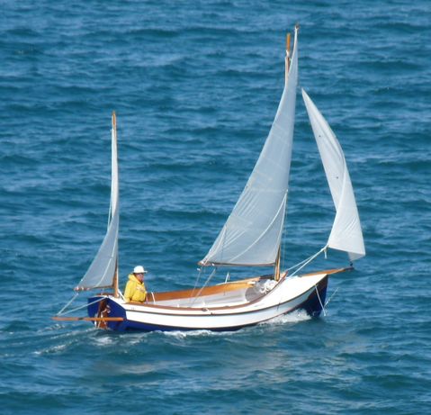
Begin with the end in mind say motivational experts! There's nothing like looking at drawings of the finished boat to strir the body into boat building action.  Above is a pic of Kees Prins drawing for my Fulmar cruising conversion with the sail plan and hull expansion I specified.  The boat dimensions (for this design is named named "Far Fetch" by Kees - i.e. taking his own design a little further) are as follows:

Lenght Overall (LOA) excluding bow sprit - 16ft 9inches - 5.10m
Lenght on Waterline (DWL) - 16ft 1 inch  - 4.90m
Beam - 6ft 4.5inches - 1.94m
Draft - 13.5inches/4 feet   -  0.34m/1.20m
Displacement 1900lbs  - 865kg
Ballast Keel Shoe - 230lbs  - 105kg
Boat Weight 1400lbs  - 640kg
Sail Area 150sq ft  - 14sq m

If you interested in building this design contact Kees Prins at keesprins@gmail.com  You will need to purchase Kees' construction plans as well as the original Iain Oughtred Fulmar plans.  You will find Iain's plans available on the web from a number of sources including Wooden Boat Magazine in the US and Jordan Boats in UK.  In Australia Iain Oughtred is represented by Robert Ayliffe of Straydogboatworks http://www.straydogboatworks.com/

For the moment the name I am giving to my boat is SKYE MAID.  This is both a tribute to outstanding  small boat design work of Iain Oughtred and reflects both his current home in the Isle of Skye and my Scottish heritage (one branch of my ancestors comes from the Isle of Skye where Iain now resides).  My previous boat, a Sunmaid 20 was named "Brigadoon".  


Saturday 30 March 2013

The Design Shortlist


Here's a brief overview of the "finalist" designs I really liked which you might call my shortlist for the main boat I will be building (more about this later).

1. (the late) Phil Bolger's Chebacco.  At 20 feet she's a bit bigger than what I really have capacity for building but I liked the look of her, her relatively lightweight and the neat positioning of rudder in front of motor and boxed keel.  Stories from builders were alluring. However cabin space was limited for a boat of this length.


2. Dudley Dix's Cape Cutter 19 has plenty of room and outboard in well. The cutter rig has a lot of appeal for me to maintain sailability in strong breeze and easily gearing up/down sail for single handing. However hull still just a little too big for my building space.

3. Pocket Ship (above) by John Harris is a very clever design in just 14 feet - I got very close to proceeding with this but couldn't quite come to grips with the sail plan  and windward ability , particularly if single handing in the strong sea breezes and southerly changes prominent around Sydney.

4. The above is Kees Prins cruising conversion of an Iain Oughtred Fulmar. This is basically the boat I am going to build - an Expanded Cruising Fulmar.  It is based on Iain Oughtred's Fulmar plans (which I already had). This design is the biggest of his family of three performance dayboats, Sheerwater, Gannet and Fulmar.  The picture above shows Kees Prins cruising cabin yawl version called Fetch. He converted this from an existing open Fulmar.  I have commissioned Kees to draw up construction plans (in consultation with Iain) for a slightly different version. Mine will be cutter rigged and wider towards the stern (using a "wedge" insert tapering from 10 inches at the stern to nil at the bow - an inspiration of my brother David Gregor an aircraft engineer and experienced sailor) with raised sheerline (4 inches at stern, 3 inches midships and 2 inches at bow).  She will be just under 17 feet. Iain Oughtred's hull and sailplan design give a slick performer which impressed me greatly in pics and videos. She is similar in size and design to the Wayfarer - a mainstay of UK Dinghy Cruising,  the most famous exponents of whom are Frank and Margaret Dye.


5. John Brooks version of the Herreshoff 12 1/2 (above) is a classic and beautiful day boat. I bought the plans for this and may still build it one day.  But Cruising Fulmar is more suitable for my current cruising needs.

6. The above is a John Welsford's 18 foot Pathfinder - big sister to 14 foot Navigator. I got close to proceeding with a sloop version of this but could not get comfortable cockpot space and cabin space without totally changing the design.

So there you have it - I am going to be building a  Cruising version of Iain Oughtred's Fulmar with assistance from Kees Prins.